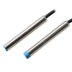
Advantages:
1)
Compact volume, Diversified exterior
2)
High precision of repeated location
3) Good performance of anti-interference
4)
High on-off frequency, Wide voltage range
5)
Dust proof, vibration proof, water proof and oil proof
6)
With short-circuit protection and inverted connecting protection
Specification:
|
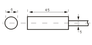
Dimension
|
|
|
|
|
|
|
|
|
|
|
|
|
|
Flush
|
Detection distance
|
1mm
|
|
|
|
NPN
|
NO
|
LJ6A3-1-Z/BX / LM6-3001NA
|
|
|
DC
|
NC
|
LJ6A3-1-Z/AX / LM6-3001NB
|
|
|
6
|
NO+NC
|
|
|
|
~
|
PNP
|
NO
|
LJ6A3-1-Z/BY / LM6-3001PA
|
|
|
36
|
NC
|
LJ6A3-1-Z/AY / LM6-3001PB
|
|
|
V
|
NO+NC
|
|
|
|
|
two wire system
|
NO
|
LJ6A3-1-Z/EX / LM6-3001LA
|
|
|
|
NC
|
LJ6A3-1-Z/DX / LM6-3001LB
|
|
|
AC
|
SRC Control label silicon
|
NO
|
LJ6A3-1-J/EZ / LM6-2001A
|
|
|
90
|
NC
|
LJ6A3-1-J/DZ / LM6-2001B
|
|
|
~250
|
NO+NC
|
|
|
|
V
|
Relay output
|
|
|
|
Non-flush
|
Detection distance
|
1.5mm
|
|
|
|
NPN
|
NO
|
LJ6A3-2-Z/BX / LM6-3002NA
|
|
|
|
NC
|
LJ6A3-2-Z/AX / LM6-3002NB
|
|
|
DC
|
NO+NC
|
|
|
|
6
|
PNP
|
NO
|
LJ6A3-2-Z/BY LM6-3002PA
|
|
|
~
|
NC
|
LJ6A3-2-Z/AY / LM6-3002PB
|
|
|
36
|
NO+NC
|
|
|
|
V
|
two wire system
|
NO
|
LJ6A3-2-Z/EX / LM6-3002LA
|
|
|
|
NC
|
LJ6A3-2-Z/DX / LM6-3002LB
|
|
|
AC
|
SRC Control label silicon
|
NO
|
LJ6A3-2-J/EZ / LM6-2002A
|
|
|
90
|
NC
|
LJ6A3-2-J/DZ / LM6-2002B
|
|
|
~250
|
NO+NC
|
|
|
|
V
|
Relay output
|
|
|
|
Control output
|
DC
|
150mA
|
|
|
SCR/Relay
|
|
|
|
Output voltage drop DC/AC
|
DC<3V
AC<10V
|
|
|
Consumption current
|
DC<15mA
AC<10mA
|
|
|
Standard detected object
|
6×6×1(A3 iron)
|
|
|
Repeated precision
|
0.01
|
|
|
DC/AC Response frequency
|
500Hz
|
|
|
Working environment temperature
|
–25℃~75℃
|
|
|
Insulation resistance
|
≥30MΩ
|
|
|
Shell material
|
Stainiess steel
|
|
|
Protection grade
|
IEC standard IP67
|
|
|
Altemative model at home and abroad
|
|
|
Series
connection and parallel connection:
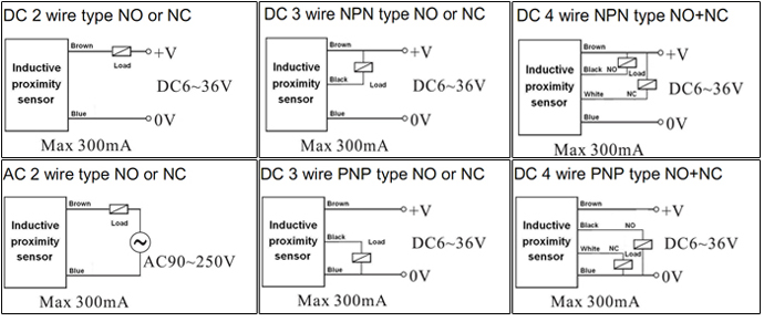
Explanation
of technical terms:
|
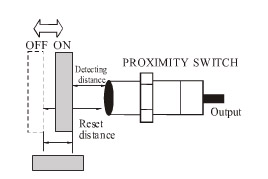
Detection distance
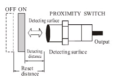
Move the
detected object according to
assigned method, the distance from
the reference position (reference plane)to the detecting
action(resetting)
|
Setting distance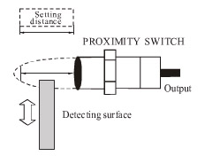
Including the
effects like temperature and voltage, without error action the distance
passed through from the practical detection surface to the objected object.
|
Standard detected object
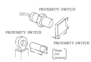
Take as
standard detected object
to detect the basic
performance. the shape,
size and material have been determined.
|
|
Differential distance
The absolute value
of the distance
difference between the distance to action and the distance To
resetting
|
Response time
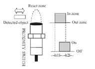
TI:when the objected object
enters the action
zone, the time from proximity
sensor being in action state to output appearance.
T2:the time from
leaving action zone
to output disappearance.
|
Response frequency
Work out the tracking output times per second by repeatedly approaching the
detected object
Brief detection method sees the above diagram
|
Main
features:
Take high frequency oscillation type proximity sensor(front
detector)as representative example to briefly explain general features of
proximity switch.
|
Item
|
Explanation
|
Features
|
◆ About
detected object
When the material of detected object is non magnetic metal, the distance of
action should descend. But when the foil material is approximately thicker
than a.01mm,the detection distance will be the same as that of magnetic
object If the film plating is extremely thin or non-conductive, detection
cannot be conducted. The effect of cladding material, take note of the
changing of detection distance.
◆ About ambient weather
In order to maintain reliable action and long service life, please avoid
the(outdoor)occasion beyond the stipulated ambient temperature. Do not drench
it with Water or water-soluble cutting lubricant when it is used with cover,
although the proximity sensor is waterproof. Do not used in the occasions
with chemical agents, especially strong base acid, nitric acid, hot strong
sulfuric acid and so on.
◆ About maintenance and overhaul
In order to keep the proximity sensor to work stably for long time, the following
regular examinations should be performed just like general control.
1. Check the installation position of
detected object and proximity sensor if any deviation, loosening or
deformation exists.
2. Check the attached wires and
connecting parts if any loosening bad contact or wire breaking off exists
3. Check if there is any metallic
powder accumulation or not
4. Check if the temperature condition
and surrounding environment condition are normal or not
5. Check if the detection distance is normal or not
|
|
The size of detected object and detection
distance
|
If the detected object
is square metal sheet with constant thickness (t=1mm), detect at detection
distance X when change its side length dmm.
X(mm)

|
When the detected object is bigger than standard
detection distance is constant. According to different Machine type,
sometimes the features will that mentioned on the left. To through type, the
detection object is like cylinder metal bar
|
|
The thickness of detected object and detection
distance
|
Detect at
detection distance Xmm(front
detector)when change the thickness of the assigned standard detected object
1mm.

|
For more than 1mm thick magnetic metal like iron
on the main, the detection distance will not change.
|
|
The effects resulted from the Thickness of
detected object and cladding material
|
Because the
detection to standard detected object will be effected by its shape,
size, material, and various cladding material, confirm
through detection distance
Xmm measurement.
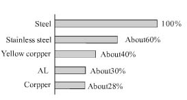
|
The effects resulted from detection distance and
cladding material of the metal excluded iron will be different according to
different machine type On the main, the machine type which detects all the
metals will not be effected by cladding material.
|
Correct
use, installation and cautions:
|
◆Mounting screw switch
◆ Do
not tighten with
over-torque when mounting
the switch. Adopt toothed washer when tightening
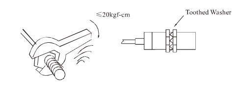
|
◆ Mounting
non screw type pillar switch
◆ When
adopt adjusting screw,
the tightening torque
should be within 2-4kgf-cm
|
|
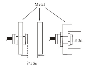
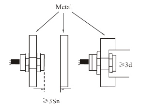
◆
Protection against the
interference of non
detected object
◆ When
mounting the proximity switch on the metal part,
do refer to the following diagram. Remain a certain space in advance according
to the shown
diagram so as
to prevent the switch from
error action
|
◆ Protection against mutual interference between
switches
◆ Mount according to
the size which
is bigger than
that in the following diagram
to prevent the
switch from error
action resulted from mutual
interference if mount the switches contra-positively or in parallel
|
|
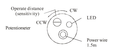
◆
Adjustable switch action distance(sensitivity)
◆ The action distance(sensitivity)of
proximity switch can be adjusted by
the means of
trimming potentiometer.
Increase the action
distance and reduce
sensitivity when turn clockwise.
Vice versa. Do
not use in
the critical state of max. action distance.
|
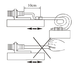
◆Guard of switch lead-wire
◆ When mount
switch, fix the
lead-wire at a
distance about 10cm from the switch with wire clip so as
to prevent the switch lead-wire from damage from outer force
|
■ Cautions
◆DC switch
should adopt insulation transformer and ensure stable voltage mains
corrugation.
◆IF any
electric power line or dynamic line passes through the surrounding of switch
lead-wire, in order to prevent the switch
from damage or error action, cover
the metal bushing on the switch lead-wire and ground it to the earth.
◆Set the
switch use distance within the rated distance to avoid the effects from
temperature and voltage
◆Wiring while power-on is strictly
prohibited. Connecting the wires
strictly according to the
wiring diagram and output
return elementary diagram.
◆If there
are any special requirements to the switch like water proof, oil proof, acid
proof, base proof, high temperature proof
or with any other specifications, the
users are required to give clear indication when placing an order. We can
produce accord
-ing to the requirements of the use.
Application
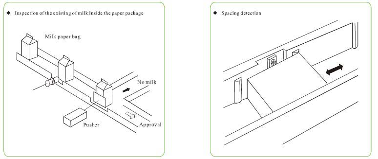
illustration of proximity switch:
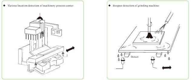 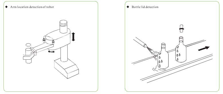 
|


