Advantages:
1) Compact volume, Diversified exterior
2) High precision of repeated location
3) Good performance of anti-interference
4) High on-off frequency, Wide voltage range
5) Dust proof, vibration proof, water proof and oil proof
6) With short-circuit protection and inverted connecting protection
Specification:
|
Dimension
|
|
|
|
|
|
|
|
|
|
|
|
|
|
Flush
|
Detection distance
|
|
|
|
|
NPN
|
NO
|
|
|
|
DC
|
NC
|
|
|
|
6
|
NO+NC
|
|
|
|
~
|
PNP
|
NO
|
|
|
|
36
|
NC
|
|
|
|
V
|
NO+NC
|
|
|
|
AC
|
SRC Control label silicon
|
NO
|
|
|
|
90
|
NC
|
|
|
|
~250
|
NO+NC
|
|
|
|
V
|
Relay output
|
|
|
|
Non-flush
|
Detection distance
|
0-17mm
|
|
|
|
NPN
|
NO
|
CM30-3017NA
|
|
|
|
NC
|
CM30-3017NB
|
|
|
DC
|
NO+NC
|
CM30-3017NC
|
|
|
6
|
PNP
|
NO
|
CM30-3017PA
|
|
|
~
|
NC
|
CM30-3017PB
|
|
|
36
|
NO+NC
|
CM30-3017PC
|
|
|
AC
|
SRC Control label silicon
|
NO
|
CM30-2017A
|
|
|
90
|
NC
|
CM30-2017B
|
|
|
~250
|
NO+NC
|
|
|
|
V
|
Relay output
|
|
|
|
Control output
|
DC
|
200mA
|
|
|
SCR/Relay
|
300mA
|
|
|
Detectable object
|
Conductor and dielectric body
|
|
|
Consumption current
|
DC<15mA AC<10mA
|
|
|
Output current
|
DC:200MA AC:300MA
|
|
|
Output voltage drop
|
DC<3V AC<7V
|
|
|
DC/AC Response frequency
|
DC:50HZ AC:10HZ
|
|
|
Working environment temperature
|
–25℃~75℃
|
|
|
Insulation resistance
|
50MΩ
|
|
|
Shell material
|
ABS resin
|
|
|
Protection grade
|
IEC standard IP67
|
|
|
Altemative model at home and abroad
|
|
|
Series connection and parallel connection:
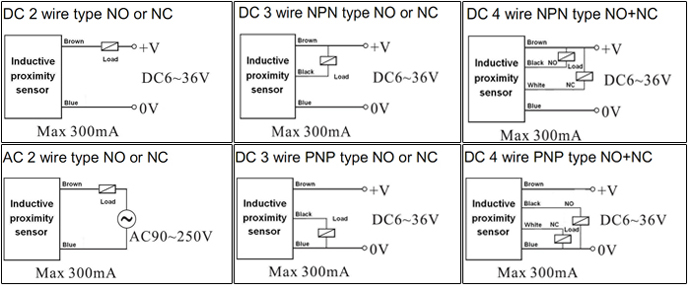
Explanation of technical terms:
|
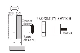
Detection distance
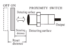
Move the detected object according to assigned method, the distance from the reference position (reference plane)to the detecting action(resetting)
|
Setting distance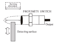
Including the effects like temperature and voltage, without error action the distance passed through from the practical detection surface to the objected object.
|
Standard detected object
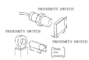
Take as standard detected object to detect the basic performance. the shape, size and material have been determined.
|
|
Differential distance
The absolute value of the distance difference between the distance to action and the distance To resetting
|
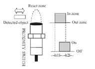
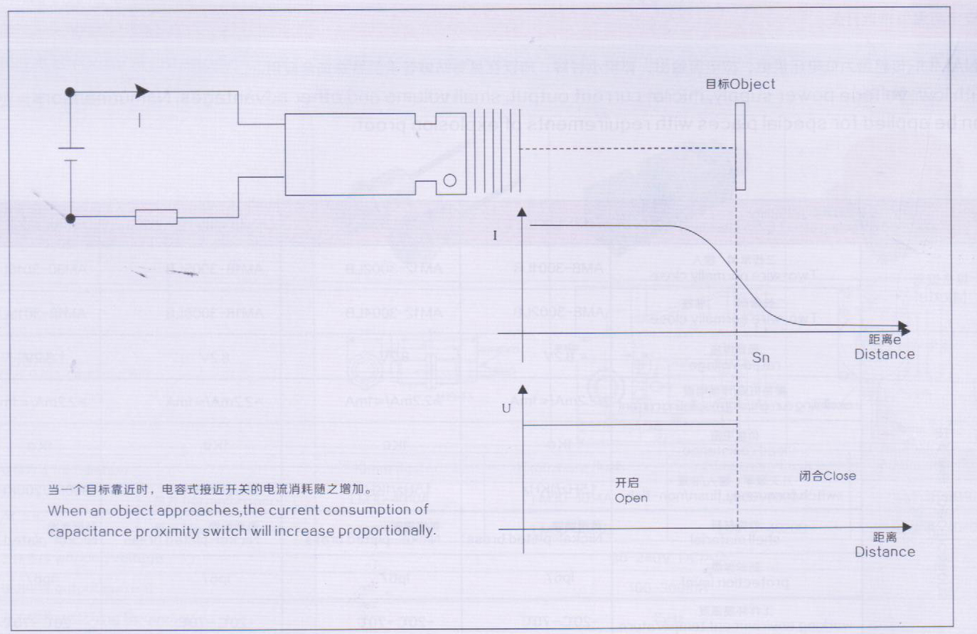
Response time
TI:when the objected object enters the action zone, the time from proximity sensor being in action state to output appearance.
T2:the time from leaving action zone to output disappearance.
|
Response frequency
Work out the tracking output times per second by repeatedly approaching the detected object
Brief detection method sees the above diagram
|
Outward appearance illustrtion:
The dielectric constants for some important materials are as; osted as below:
|
Materials
|
Dielectric constant
|
Materials
|
Dielectric constant
|
|
Synthetic resin adhesive
|
3.6
|
Styrene
|
3
|
|
Mica
|
6
|
Porcelain
|
4.4
|
|
Ebonite
|
4
|
Petrolin
|
2.2
|
|
Marble
|
8
|
Quartz sand
|
4.5
|
|
Paper
|
2.3
|
Soft rubber
|
2.5
|
|
Organic glass
|
3.2
|
Water
|
80
|
|
Alcohol
|
25.8
|
Glass
|
5
|
|
Cardboard
|
4.5
|
Cable rubber compound
|
2.5
|
|
Gasoline
|
2.2
|
Wood
|
2.7
|
|
Polyvinyl
|
2.9
|
Quartz glass
|
3.7
|
|
Silicon
|
2.8
|
|
|
Correct use, installation and cautions:
|
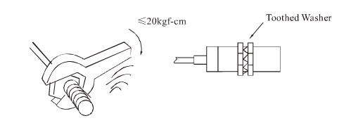
◆Mounting screw switch
◆ Do not tighten with over-torque when mounting the switch. Adopt toothed washer when tightening
|
◆ Mounting non screw type pillar switch
◆ When adopt adjusting screw, the tightening torque should be within 2-4kgf-cm
|
|
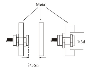
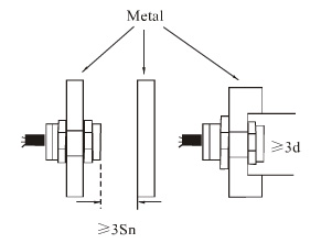
◆ Protection against the interference of non detected object
◆ When mounting the proximity switch on the metal part,
do refer to the following diagram. Remain a certain space in advance according to the shown diagram so as to prevent the switch from error action
|
◆ Protection against mutual interference between switches
◆ Mount according to the size which is bigger than that in the following diagram to prevent the switch from error action resulted from mutual interference if mount the switches contra-positively or in parallel
|
|
◆ Adjustable switch action distance(sensitivity)
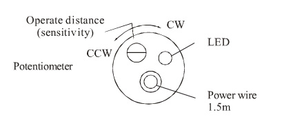
◆ The action distance(sensitivity)of proximity switch can be adjusted by the means of trimming potentiometer. Increase the action distance and reduce sensitivity when turn clockwise. Vice versa. Do not use in the critical state of max. action distance.
|
◆Guard of switch lead-wire
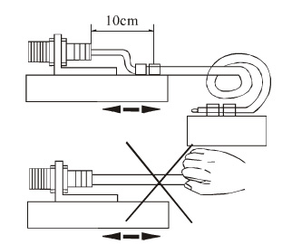
◆ When mount switch, fix the lead-wire at a distance about 10cm from the switch with wire clip so as to prevent the switch lead-wire from damage from outer force
|
■ Cautions
◆DC switch should adopt insulation transformer and ensure stable voltage mains corrugation.
◆IF any electric power line or dynamic line passes through the surrounding of switch lead-wire, in order to prevent the switch
from damage or error action, cover the metal bushing on the switch lead-wire and ground it to the earth.
◆Set the switch use distance within the rated distance to avoid the effects from temperature and voltage
◆Wiring while power-on is strictly prohibited. Connecting the wires strictly according to the wiring diagram and output
return elementary diagram.
◆If there are any special requirements to the switch like water proof, oil proof, acid proof, base proof, high temperature proof
or with any other specifications, the users are required to give clear indication when placing an order. We can produce accord
-ing to the requirements of the use.
Application illustration of proximity switch:
  
|


